Quality control and characterization tests are carried out to determine the physical, chemical, mechanical and functional properties of materials used for military and civilian purposes.
Non-destructive quality control laboratory which was constructed at 2004, is a part of quality control division. Laboratory personnel (4 engineers and 2 technicians) are certificated according to EN ISO 9712. Radiographic inspection, ultrasonic inspection, magnetic particle testing, liquid penetrant testing and visual inspection systems available in non-destructive quality control laboratory, are described below.
Radiographic Inspection Capabilities:
X-Ray System (Y. Access 100 X-Ray System):
Y. Access 100 X-Ray has 450 kV mini focus tube and 14 bit flat panel detector. The system is capable of moving in 4.5x9 m2 space.
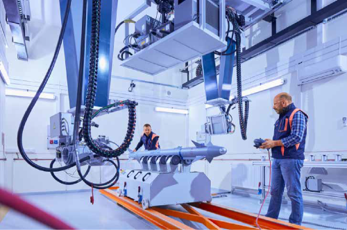
Figure 1. Y. Access 100 X-Ray System
The workbench was specially designed to meet all testing requirements. Samples have length of 8000 mm and diameter of 1000 mm can be inspected by using this x-ray system and the workbench.
X-Ray Tomography System (Y.CT Modular X-Ray System):
Y.CT Modular X-Ray System is used for 2-dimensional and 3-dimensional X-ray inspection (computed tomography) has 450 kV mini focus tube, 225 kV micro focus tube and 16 bit flat panel detector. Samples have length of 500 mm, diameter of 320 mm and weight of 50 kg can be inspected by using CT Modular system. The penetration depth of x-ray beam in a bulk steel is about 65 mm. Failure analysis, thickness analysis, geometric measurements and nominal/actual comparison is possible on 3-dimensionally inspected parts.
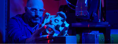
Figure 2. X-Ray Tomography System (Y.CT Modular X-Ray System)
X-Ray Systems for Electronics
Y. Cougar SMT X-Ray System: Y.Cougar X-Ray System has 160 kV multi focus tube and 14 bit flat panel detector. It is used for 2-dimensional X-ray inspection of printed circuit boards (PCB’s) and electronic assemblies.
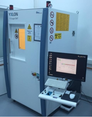
Şekil 3. Y. Cougar SMT X-Işını Sistemi
Y. Cheetah SMT X-Ray System: Y.Cheetah X-Ray System has 160 kV multi focus tube and 16 bit flat panel detector. It is used to inspect printed circuit boards (PCB’s) and electronic assemblies. Apart from the other x-ray system, computed laminography and computed tomography options are available.

Şekil 4. Y. Cheetah SMT X-Işını Sistemi
Ultrasonic Test Capabilities:
Ultrasonic inspection is a bulk inspection technique which is preferred for the detection of internal imperfections that cannot be observed with radiography. Two conventional ultrasonic test equipment, (EPOCH 4PLUS, GE USM GO) and one phased array ultrasonic test equipment (Olympus OmniScan MX2) are available in non-destructive testing quality control laboratory.
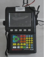

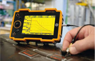
Figure 6. Ultrasonic Test Equipment (EPOCH 4PLUS, Olympus OmniScan
MX2, GE USM GO)
Magnetic Particle Testing Capabilities:
Magnetic particle testing is used for the detection of surface/subsurface imperfections in ferromagnetic materials. Test can be performed under UV or visible light.
For magnetic particle inspection, AC&DC hand yoke (AC 230V, 50Hz) and MP 2500 AC_FWDC Magnetic Particle Testing System are available in non-destructive testing quality control laboratory.

Figure 7. MP 2500 AC_FWDC Magnetic Particle Testing System
Ferromagnetic samples have length of 2500 mm and diameter of 500 mm can be inspected by using MP 2500 AC_FWDC Magnetic Particle Testing System and surface/subsurface imperfections can be detected.
Liquid Penetrant Testing Capabilities:
Discontinuties open to the surface of a material can be detected by liquid penetrant testing. The material surface should be clean and uncoated to allow the penetration of liquid dye into the discontinuties. Test can be performed under UV or visible light.
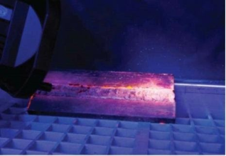
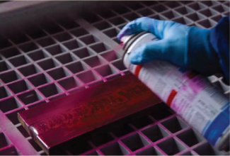
Figure 8. Liquid Penetrant Inspection
Visual Inspection Capabilities:
Surface discontinuties are inspected by qualified personnel using visual inspection techniques. These techniques includes use of some lighting and measurement tools like torch, callipers, magnifying glass etc. For the visual inspection of non-reachable parts of the specimens, Videoscope Instrument has a fiber-optic cable with 6 mm diameter and 2 m length (GE Mentor Visual IQ VideoProbe) is used.
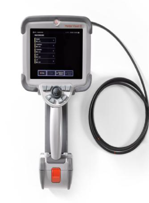
Figure 9. GE Mentor Visual IQ VideoProbe Videoscope Instrument
The successful employment of parts in defence applications relies on the ability of the raw materials to meet design and service requirements. The capability of a part to meet these requirements is determined by the physical, chemical and mechanical properties of the starting material using in manufacturing stage. Mechanical properties, are described as the relationship between forces (or stresses) acting on a material and the resistance of the material to deformation (i.e., strains) and fracture. In Materials Quality Control Laboratory, different types of tests are used to determine properties, such as modulus of elasticity, yield strength, tensile strength, elastic and plastic deformation (i.e., elongation).
Tension/Compression Test Machine
Two identical Instron 5982 Dual Column Floor Model testing systems shown in Figure 1 is used in mechanical tests. A variety of load cells (1 kN, 10kN, 100kN) are available to provide accurate measurements for applications ranging from weak elastomers to those utilizing the full capacity of the load frame. Additionally, a full range of grips, fixtures, and strain measurement devices (Video extensometer and clip on extensometers) are also available.
Some important features of the instrument is given below.
- 1 kN, 10 kN, 100 kN capacity load cells provide a wide range of test capability.
- Environmental Cabinets can be used between -75°C and +180°C temperature interval.
- 8 mm and 16 mm focal length Video Extensometer and 25/50 mm gauge length dynamic clip-on extensometer ensure high reliability and repeatibility on test result.
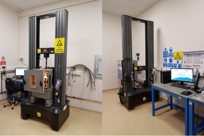
Figure 1. Instron 5982 Dual Column Floor Model Testing Systems
Some examples of mechanical tests made in the Materials Quality Control Laboratory are shown in Figure 2 and Figure 3.
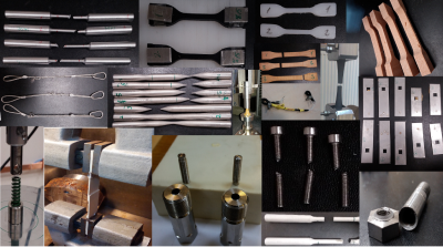
Figure 2. Mechanical Test Examples
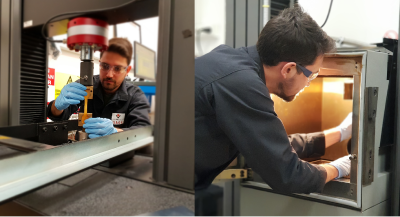
Figure 3. Tension Test Application
Dynamic Test (Fatigue) Instrument
Fatigue is a form of failure that occurs in structures under dynamic and cyclic stresses. (e.g., bridges, aircraft, and machine parts.) Normally, this type of failure occurs after a lengthy period of repeated stres sor strain cycling. It is catastrophic and insidious, occuring suddenly and without warning.
The Instron ElectroPuls E10000 (See Figure 4), used in the Materials Quality Control Laboratory, is an test instrument designed for dynamic and static testing on a wide range of materials and components. Some important features of the instrument is given below.
- Oil-free linear motor technology for clean test conditions
- Capable of operating at over 100 Hz
- ±10 kN dynamic linear load capacity and ±100 Nm dynamic torque capacity
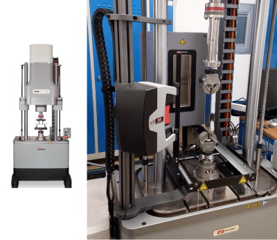
Figure 4 Dynamic Test (Fatigue) Instrument
Environmental Chambers
Conditioning of the test specimens in accordance with desired test procedures is made by climatic and thermostatic chambers. In the laboratory there are four different types of chambers. (See Figure 5 and Figure 6) Three of them are integrated to the universal testing machines and one is used independently. Temperature range of chambers are up to -75 0C for cooling and +180 0C for heating.
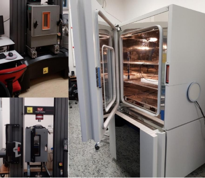
Figure 5 Climatic and Thermostatic Chambers
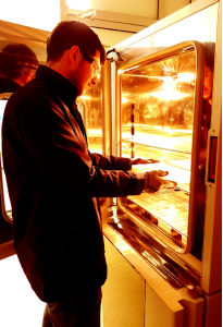
Figure 6 Environmental Chamber Example
Rockwell Hardness Tester
One of the characteristic test conducted on metallic materials (especially in heat treated parts) is Rockwell Hardness Test. The Rockwell hardness test can provide useful information about metallic materials. This information may correlate to tensile strength, wear resistance, ductility, and other physical characteristics of metallic materials, and may be useful in quality control and selection of materials. The Rockwell hardness tester and measurement application example can be seen in Figure 7
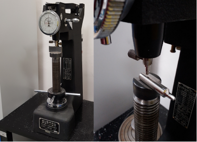
Figure 7 Rockwell Hardness Tester
Shore Hardness Tester (Durometer)Optik Emisyon Spektral Analizi
Durometer (See Figure 8) is an instrument that is widely used to determine the hardness of many organic materials like soft rubber, elastomers,natural rubber products,neoprene, casting resin,polyester, soft PVC, leather, etc ... Hardness measurements can be carried out easily in various methods (A, B, C, D, DO, E, M, O, OO, OOO, OOO-S, R) by changing applied force and the indenter type of the durometer.
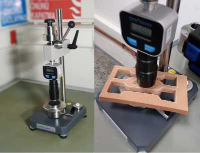
Figure 8 Durometer and Hardness Measurement
Optical Emission Spectrometer
The chemical composition requirements is determined by the Optical Emission Spectrometer with Argon flushed spark stand for quantitative spectrochemical analysis of metal samples. As with all emission phenomena, optical emission involves the expulsion of photons as electrons in excited states drop back to lower states. In the case of optical emission, the process involves the excitation or ejection of outer shell (or valence) electrons. The line spectra produced by these electron transitions are characteristic of the element involved. The Optical Emission Spectrometer can be seen in Figure 9.
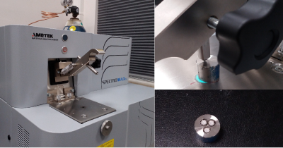
Figure 9 The Optical Emission Spectrometer
X-Ray Fluorescence (XRF) Analyzer
X-Ray Fluorescence is defined as secondary X-rays from a material that has been excited by bombarding with high-energy X-rays. When high energy photons are emitted from an X-rays source to a substance, they are absorbed by atoms and inner shell electrons are ejected from the atom. This leaves the atom in an excited state, with a vacancy in the inner shell. Outer shell electrons then fall into the vacancy, emitting photons with energy equal to the energy difference between the two states. Since each element has a unique set of energy levels, each element emits a pattern of X-rays characteristic of the element, termed “characteristic X-rays”. By analyzing intensity of characteristic X-rays, the chemical composition of any material can be can be calculated. The phenomenon is widely used for analysis of elements starting from sodium to uranium in the periodic table. XRF Analyzer (Figure 10 and Figure 11) is shown below.
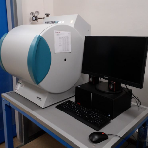
Figure 10 X-Ray Fluorescence (XRF) Analyzer
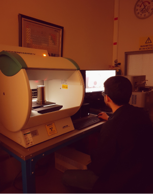
Figure 11 Elemental Analisis by Using XRF Analyzer
Geometrik ve Form Ölçümleri
Birbirine montajı yapılan ürünlerin form özellikleri son derece önem arz etmektedir. Form hatası, ürünün şeklinin ilgili geometrik şekilden sapması olarak tanımlanmaktadır.
Dairesellik ve Form Ölçüm Kabiliyetleri
Form ölçümleri aşağıda belirtilen hassasiyetlerde yapılabilmektedir.
Dairesellik Belirsizliği: (0.02 + 0.0005) µm
Silindiriklik Belirsizliği : 0.15 µm (100 mm’de)
Salgı, eş eksenlilik, diklik, paralellik hassasiyeti (100 mm’de): 0.4 µm
Ölçüm Parçası Sınırlamaları;
Parça Uzunluğu(Maksimum) : 470 mm
Parça Ağırlığı (Maksimum) : 60 kg
İç Çap (Maksimum ) : Ø364mm
Dış Çap (Maksimum) : Ø280mm
Form Kontür Ölçüm Kabiliyetleri
Genellikle endüstriyel uygulamalar için kullanılır ve nesnelerin ölçülerini, şekillerini ve geometrik detaylarını belirlemek için kullanılır. Ölçüm, 0.05 mm’den büyük radius, pah, kademe vb. formlarda ±(0.25 + H/250) µm belirsizliğinde ölçüm yapılabilmektedir.
Parça Uzunluğu(Minimum) : 0,01 mm
Parça Uzunluğu(Maksimum) : 140 mm
Parça Ağırlığı (Maksimum) : 90 kg
İç Çap Tarama Uzunluğu minimum Ø3 mm’dir.
Hassas Boyut Ölçüm Kabiliyetleri
Yüksek hassasiyet gerektiren boyut, iç ve dış çaplarda ±0.09 L / 2000 µm belirsizlikle ölçüm yapılabilmektedir.
Dış çap ölçüm kapasitesi: 0 – 300 mm arası
İç çap ölçüm kapasitesi: 5 -150 mm arası
Parça Ağırlığı (Maksimum) : 11 kg
Üç Boyutlu Ölçümler (Koordinat Metrolojisi-CMM)
Koordinat ölçme sistemi ile Kartezyen koordinatına göre ölçüm yapılmaktadır. X,Y ve Z ekseninde hareket eden sistemin proba bağlı kafası 360 derece kendi ekseninde dönerek çok yönlü ölçüm imkanı vermektedir. Camio ve PC-DMIS yazılımları kullanılmaktadır. Teknik eğitim, parça program yazılımı, program doğruluk kontrolleri yapabilme teknik yetkinlik ve kabiliyeti mevcuttur.
Cihaz Ölçüm Belirsizliği: 0,5 + L/500 µm (Minimum)
Farklı Eksenlerdeki ölçüm yapma kapasitesi;
X ekseni: 700 mm (minimum), 1500 mm (maksimum)
Y ekseni: 1000 mm (minimum), 3300mm (maksimum)
Z ekseni: 650 mm (minimum), 1350 mm (maksimum)
Yüzey Pürüzlülüğü Ölçümleri
Ürünlerin yüzey pürüzlülüğü, mekanik ve fiziksel özelliklerini önemli ölçüde etkilemektedir. İstenilen yüzey kalitesi, amaca uygun üretim yöntemlerini seçerek ve kontrol ederek elde edilir. Ürünlerde, sürtünme, aşınma, geçme, sızdırmazlık, yorulma, yapışma, optik yüzey, elektriksel ve termal kontak gibi arzu edilen fiziksel özellikler üretim yöntemleri ile ayarlanabilir.
Tüm yüzey parametrelerinin (Ra, Rq, Ry, Rz vb.) değerinde çıktı sağlanmaktadır.
Ölçüm aralığı : ± 250 µm (3 x prob kolu uzunluğu ile ±750 µm seviyesine kadar)
Profil çözünürlüğü: Ölçme aralığı ± 250 µm: 8 nm
Ölçme aralığı ± 25 µm: 0,8 nm
Ölçme aralığı ± 500 µm: 16 nm
İç Çap Profil Yüzeyi Ölçüm Kapasitesi: min Ø25 mm çapta 125 mm derinliğe kadar
İç Çap Profil Yüzeyi Ölçüm Kapasitesi: min Ø5 mm çapta 75 mm derinliğe kadar
Chemical Quality Control Laboratory, which is a part of quality control division, meets the characterization and quality control requirements of propellants, pyrotecnics, explosives and other different types of chemicals such as polymers, composites and insulation materials.
Kimyasal Kalite Kontrol Laboratuvarı’nda 2 araştırmacı ve 3 teknisten ile çalışmalar yürütülmektedir. Aşağıda laboratuvarımızda bulunan cihazlar ve bu cihazlar ile gerçekleştirilen çalışmalar hakkında bilgiler verilmektedir. Cihazlar hakkında ayrıntılı bilgiler ayrıca bir tablo halinde verilmiştir. Aletli analizler harici gerçekleştirilen analizler ile ilgili bilgiler de ayrıca tablo halinde belirtilmiştir.
Dynamic Mechanical Analyzer (DMA)
DMA is used to analyze the mechanical properties of a material by changing temperature and frequency. Materials such as films, solid polymers, foams and composites can be tested in DMA. Glass transition temperatures (Tg) can be detected and viscoelastic properties of materials can be studied by using appropriate clamps. Aging information of materials can also be obtained from DMA studies by time-temperature superposition experiments
(TTS). Exceptional cases are given below:
- Crystals. Partial melting in the working temperature range.
- The change in the structure of material by temparture
- Block co-polymers
- Materials consisting of different types of polymers
- Polymers showing different viscoelastic mechanisms rather than configurational changes.
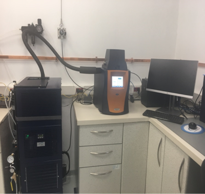
Şekil 1. DMA CİHAZI
High Performance Liquid Chromatography (HPLC) Analysıs
High Performance Liquid Chromatography (HPLC) is a qualitative and quantitative technique for determination of chemical constituents. There should be reference calibration materials, appropriate columns and dedectors for analytes.
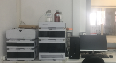
Şekil 2. HPLC CİHAZI
Thermal Analysıs
Diferential Scanning Calorimeter (DSC)
DSC analyzes the changes of physical properties of a material with respect to temperature. Glass transition temperature (Tg), melting point (Tm) , crystallization point (Tc), Decomposition temperature (Td), thermal and oxidation stability, thermal capacity (Cp) and curing time can be studied with DSC.
Before starting DSC analysis, the material is inspected in TGA to determine the decomposition temperature and the analysis are performed under decomposition temperature for safety reasons. (Some materials can damage the sample pan and instrument at high temperatures.)
There are two types of DSC in the laboratory. Diamond DSC is working from room temperature to 550°C, DSC 2500, equipped with an autosampler, is working in the range -120°C to +750°C with appropriate accessories.
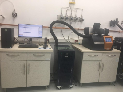
Figure 3. DSC 2500
Thermogravimetric Analyser (TGA)
TGA analyzes the weight changes in a given temperature range with temperature scanning or isothermal test methods. Working ranges can be chosen in between room temperature up to 1000 °C or 1500 °C. Testing environment can be chosen as nitrogen, oxygen or argon.
It is also possible to determine the aging profile of samples by using kinetic models and compatibilities of two or three materials. There are two types of TGA instruments in CQCL with vertical and horizontal ovens.
STA VE TGA Resimleri
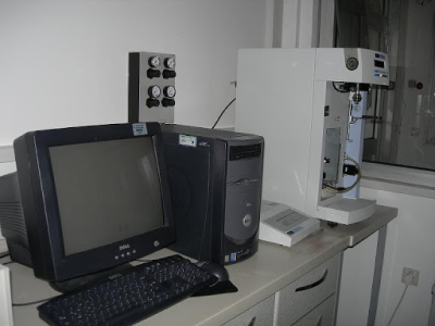
Figure 5. TGA (vertical oven)
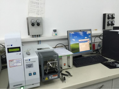
Figure 6. TG-DTA (horizontal oven)
FTIR Analyzer:
Fourier Transformed Infrared Analyzer gives information about the chemical bonds in a molecule. One can determine the functional groups, characterize the molecular bonds, compare materials and follow the differences in their structure wrt time. FTIR is working between 400-4000 cm-1 and has diamond and germanium ATR (Attanuated Total Reflectance) and Diffuse Reflectance accesorizes.
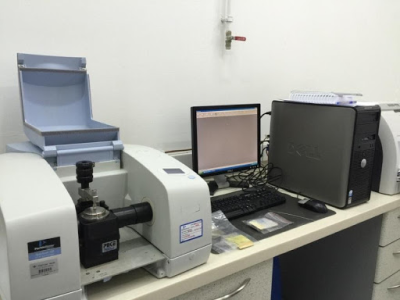
Figure 7. FTIR
Water Content Analysis
Karl Fischer titrations are used for determination of humidity/water content of materials. There are two types of devices as coulometric and volumetric for low water contents (1 ppm-5 %) and high water contents (above 5%) respectively. In addition, an oven which can work up to 280°C with an autosampler can be connected to coulometric titrator for fast and easy measurements.

Figure 8. Karl Fischer Coulometric and Volumetric Titrators
Density Measurements
True density of materials can be measured by Helium pycnometer. Tap and bulk density of powders can also be determined in the laboratory.

Figure 9. Helium Pycnometer
Stojan Vessel
Burning rates of propellants can be determined by using Stojan Vessel. In this technique, burning data can be collected up to 500 bars, and results can be calculated for every required pressure value. Test samples can be conditioned between -70°C and +180°C. For the samples conditioned below room temperatures X-ray analysis must be performed previously to detect any deformations in the structure of sample. It is also possible to use this device as a close bomb. All test requests will be evaluated by our laboratory before application in terms of work safety.
The required sample sizes for Stojan Vessel are given below:
- Disc samples : thickness (e0) 10 mm ± 5 mm and length: 60 mm ± 20 mm.
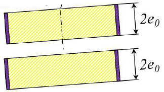
Figure 10. Disc samples
-
Tube samples: thickness (e0) 10 mm ± 5 mm , diameter 30 mm ± 10 mm, length < 10x (diameter-2x thickness)
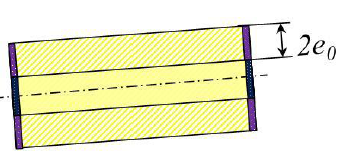
Figure 11. Tube samples

Figure 12. Control Unit

Figure 13. Firing Unit

Figure 14. Stojan Vessel
Calorific Value Tests (Oxygen Bomb)
The released energy of a material is determined during its combustion by calorimeters. The energy value is given as cal/g or J/g. Tests can be performed under oxygen, argon or nitrogen atmosphere. The usage of oxygen must be evaluated before tests for safety reasons.

Figure 15. Calorimeters
Impact Sensivity tests
These tests are performed to determine the impact sensitivity of energetic materials. BAM apparatus is used for impact sensitivity tests. 1,2 or 5 kg weights are dropped from max. 100 cm. Tests are performed and reported according to STANAG 4489 or TS EN 13631-4.
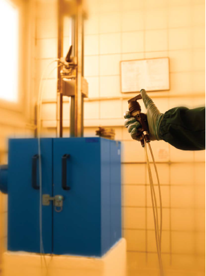
Figure 16. Impact Sensitivity Test Apparatus
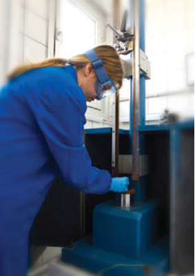
Figure 17. BAM Impact Sensitivity Test Apparatus-Sampling
Friction Sensivity Tests
These tests are performed to determine the friction sensitivity of energetic materials. BAM apparatus is used for friction sensitivity tests. Nine different weights are used in the range of 200 g to 10 kg to create friction forces. Tests are performed and reported according to STANAG 4487 or TS EN 13631-3.
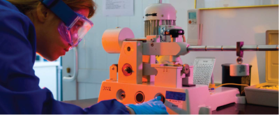
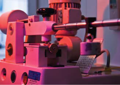
Figure 18. BAM Friction Sensitivity Test Apparatus
Thermal Conductivity Coefficient Analyzer:
Polymers, foams or ceramic materials can be tested in a temperature range of -70 °C to +180 °C. Sample size must be 5 mm in thickness and 25 mm in diameter.
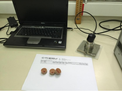
Figure 19.Thermal Conductivity Coefficient Analyzer
UV-VIS Spectrophotometer
Chemical content analysis can be done quantitatively and qualitatively by UV-VIS spectrometer. The samples must be prepared in liquid form and calibration curves are needed for qualitative analysis.

Figure 20. UV-VIS Spektrophotometer
Viscosity Measurement
Viscosity measurements can be done by dynamic and kinetic test devices. 500 mL samples are needed to perform dynamic analysis by Brookfield Viscometer. Kinetic viscosity can be measured from 25 °C to 100°C in the range of 0,5-600 mm2/s . Sample size must be 100 mL for kinetic measurements.

Figure 21. Kinematic Viscometer
5- ELEKTRONİK KALİTE KONTROL LABORATUVARI
Elektronik Kalite Kontrol Laboratuvarında 3 mühendis ve 5 teknisyen çalışmaktadır. Altyapıda kalite kontrol muayene yöntemleri olarak dizgi öncesi ve dizgi sonrası baskı devre kartların, bileşenlerin ve lehimleme işçiliğin kalite kontrolleri, kablaj testleri, akrilik kaplama kontrolleri ve elektrostatik boşalma testleri yapılabilmektedir. Bu yöntemlerde kullanılan cihazlar ve cihazların kapasiteleri ile ilgili bilgiler aşağıda verilmiştir.
Lehim dolgusu ve bileşen hasarı kontrolü
Bileşen var mı / yok mu, yön bilgisi doğru mu / yanlış mı kontrolü yapıldıktan sonra, IPC-610 standardının Sınıf 3 gereksinimlerine göre, lehim dolgusu ve bileşen hasarı gibi özellikler görsel olarak kontrol edilir. Görsel muayenede, masa üstü büyüteç, stereo mikroskop, HD yüksek çözünürlüklü kamera ve AOİ ( Optik İnceleme Cihazı) gibi A/G/A ve sistemlerinden faydalanılır.
- Stereo Mikroskop : Elektronik Kalite Kontrol Altyapısı’nda 3 farklı mikroskop tipi vardır ve bunlar “40X”, “90X” ve “200X” büyütme kapasitelerine sahiptir. “90X” büyütme kapasitesine sahip mikroskop, görüntüyü kendi ekseni etrafında 360° çevirebilme ve tepeden 36° açıyla görüntüleyebilme özelliğine de sahiptir.
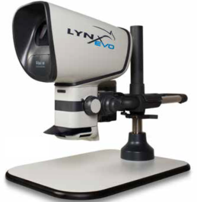
Şekil 1: “90X” Büyütebilen Mikroskop
- AOI (Optik İnceleme Cihazı)
- AOI cihazı ile muayene yapabilmek için kartın şematiği, gerber data bilgileri kullanılarak oluşturulmalı ve program yazılmalıdır. Kartın şematik bilgisi cihaza tanımlandıktan sonra elektronik bileşenlerin tiplerine göre boyutsal özellikler, lehim dolgusu, yön bilgisi gibi muayene kriterleri tek tek tanımlanır. Tanımlanmış bilgiler ve program, cihazın veri tabanına kayıt edilir ve aynı tip kart muayenesi yapıldığında ilgili program kullanılarak hızlı bir şekilde muayene yapılabilir. AOI cihazının muayene yetenekleri aşağıda verildiği gibidir;
- Tespit Edilebilir Bileşen Hata Tipleri; Kayıp, kayık, eğik, hatalı yöne sahip, dikilmiş, kalkık, ters, yanlış, hasarlı bileşenler gibi hata tiplerini tespit edebilme özelliğine sahiptir.
- Lehim Hata Tipleri; Krem lehim, dalga lehim veya elle lehimleme için; kısa devre, kılcal kısa devre, lehimsiz, az veya fazla lehimli, kısmi lehimleme, uygunsuz lehim topları gibi hata tiplerini tespit edebilme özelliğine sahiptir.
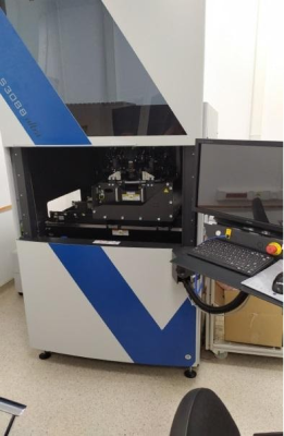 Şekil 2: AOI Cihazı
AOI cihazı ile kart muayene yapılabilmesi için kartın ya panelli bir şekilde gelmesi ya da kart kenarından en yakın bileşen pedine kadar en az 5 mm mesafe olması gereklidir.
AOI Cihazının teknik özellikleri;
- Numune Boyutu: 508 mm X 508 mm boyutundaki PCB (max)
- Çözünürlük: “40 fps for 8,3 Fm/pixel resolution in high-resolution mode”
- 0,5 µm çözünürlük Z yönü boyunca
- Ölçüm Yöntemi: “Fringe projector for 3D analyses”
Konformal Kaplama Görsel Muayene Esasları
Elektriksel testleri tamamlanmış, elektronik kart donanımlarını, çevresel şartlardan korumak için konformal kaplama uygulanır. Uygulan konformal kaplamanın kalite kontrolü gerçekleştirilirken mor ışık altında kaplamanın homojenliğine, hava kabarcıklarına, dalgalanmalara ve gerekli yerlerde akrilik kaplamanın olup-olmadığına bakılır.
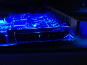
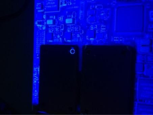
Şekil 3: Konformal Kaplamanın Mor Işık Altında İncelenmesi
Kablajların Kalite Kontrol Esasları
Üretimi tamamlanan kablajların, IPC-620 standartının Sınıf 3 kriterlerine ve ilgili kaynak belgedeki gereksinimlere göre elektriksel test ve görsel muayene işlemleri yapılır.
Elektriksel test adımında;
- İletkenlik testi,
- Kısa devre,
- Yalıtım
- HiPot testleri
yapılabilmektedir. Elektriksel testler için 32 port girişi olan ve 1500 VDC gerilim verebilen bir cihazla testler yürütülmektedir.
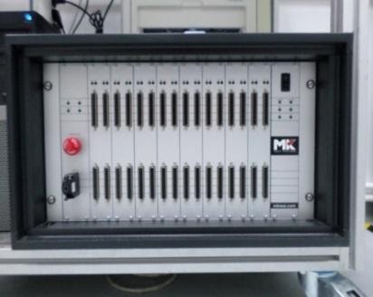
Şekil 4: Kablaj Test Cihazı
Anten kablajlarına RF testi uygulayabilmek için 100kHz-8 Ghz arasında ölçüm alabilen bir Network analizör cihazı bulunmaktadır. Bu cihazla VSWR, Sinyal kaybı gibi özellikler incelenmektedir.
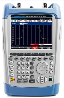
Şekil 5: Network analizör
Görsel muayene adımında, kablajın konektör hasarı, pin hasarı, makaron/kablo kılıf hasarı, konektörün kablo çıkış yönü gibi özelliklere bakılır.
Elektrostatik Boşalma Testi
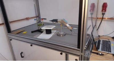
Şekil 6: ESB Cihazı
ESB Cihazı : 330/500/5000 MOhm, 2kV-25kV test gerilim aralığı. “Air” ve “Contact” ile pozitif ve negatif “discharge” kapasitesiyle bilgisayar ile veya manuel olarak çalışabilmektedir.
Kimyasal Kalite Kontrol Laboratuvarı Cihaz Marka/Model ve Teknik Özellikleri
| Instrument | Model | Technical Specifications |
| Thermogravimetric Analyzer (TGA) | Perkin Elmer –Pyris 1 TGA |
|
| Thermogravimetric- DifferentialThermal Analyzer (TG-DTA) | Hitachi SII- TG/DTA 6300 |
|
| Differantial Scanning Calorimeter (DSC) | Perkin Elmer Diamond DSC |
|
| Differantial Scanning Calorimeter (DSC) | TA Instruments-DSC 2500 |
|
| Dynamic Mechanic Analyzer (DMA) | TA Instruments- DMA 850 |
|
| UV-VIS Spectrophotometer | AnalylytkJena-Specord 50 Plus |
|
| Kinematic Viscometer | Biolab/ Viscol 10a |
|
| FTIR Analyzer | Perkin Elmer-Spectrum 100 |
|
| Calorimeter (Oxygen Bomb) | Parr – 6200 Isoperbol Calorimeter |
|
| Helium Pycnometer | Micromeritics- Accupyc II 1345 |
|
|
Shore A Hardness |
Zwick |
|
| Tap Density Tester | Engelsmann-Type Stav 2 |
|
| BAM Impact Sensitivity Test Apparatus | BAM Araştırma Enstitüsü |
|
| BAM Friction Sensitivity Test Apparatus | BAM Araştırma Enstitüsü |
|
| Volumetric Karl Fischer Titrator | Mettler Toledo-V30 |
|
| Cuolometric Karl Fischer Titrator | Mettler Toledo-C30S |
|
| HPLC Analyzer | Agilent- HPLC 1260 |
|
| Brookfield Viscometer | Brookfield DV II+Pro |
|
| Stojan Vessel (Burning Rate of Propellants) | OZM- SV2 |
|
| Sieve Shaker | Retsch |
|
| Thermal Conductivity Coefficient Analyzer | C-Therm TCi |
|
| Climatic Chamber | Angelantoni- Discovery DM 340 |
|
Elektronik Kalite Kontrol Laboratuvarında 3 mühendis ve 5 teknisyen çalışmaktadır. Altyapıda kalite kontrol muayene yöntemleri olarak dizgi öncesi ve dizgi sonrası baskı devre kartların, bileşenlerin ve lehimleme işçiliğin kalite kontrolleri, kablaj testleri, akrilik kaplama kontrolleri ve elektrostatik boşalma testleri yapılabilmektedir. Bu yöntemlerde kullanılan cihazlar ve cihazların kapasiteleri ile ilgili bilgiler aşağıda verilmiştir.
Lehim dolgusu ve bileşen hasarı kontrolü
Bileşen var mı / yok mu, yön bilgisi doğru mu / yanlış mı kontrolü yapıldıktan sonra, IPC-610 standardının Sınıf 3 gereksinimlerine göre, lehim dolgusu ve bileşen hasarı gibi özellikler görsel olarak kontrol edilir. Görsel muayenede, masa üstü büyüteç, stereo mikroskop, HD yüksek çözünürlüklü kamera ve AOİ ( Optik İnceleme Cihazı) gibi A/G/A ve sistemlerinden faydalanılır.
- Stereo Mikroskop : Elektronik Kalite Kontrol Altyapısı’nda 3 farklı mikroskop tipi vardır ve bunlar “40X”, “90X” ve “200X” büyütme kapasitelerine sahiptir. “90X” büyütme kapasitesine sahip mikroskop, görüntüyü kendi ekseni etrafında 360° çevirebilme ve tepeden 36° açıyla görüntüleyebilme özelliğine de sahiptir.

Şekil 1: “90X” Büyütebilen Mikroskop
- AOI (Optik İnceleme Cihazı)
- AOI cihazı ile muayene yapabilmek için kartın şematiği, gerber data bilgileri kullanılarak oluşturulmalı ve program yazılmalıdır. Kartın şematik bilgisi cihaza tanımlandıktan sonra elektronik bileşenlerin tiplerine göre boyutsal özellikler, lehim dolgusu, yön bilgisi gibi muayene kriterleri tek tek tanımlanır. Tanımlanmış bilgiler ve program, cihazın veri tabanına kayıt edilir ve aynı tip kart muayenesi yapıldığında ilgili program kullanılarak hızlı bir şekilde muayene yapılabilir. AOI cihazının muayene yetenekleri aşağıda verildiği gibidir;
- Tespit Edilebilir Bileşen Hata Tipleri; Kayıp, kayık, eğik, hatalı yöne sahip, dikilmiş, kalkık, ters, yanlış, hasarlı bileşenler gibi hata tiplerini tespit edebilme özelliğine sahiptir.
- Lehim Hata Tipleri; Krem lehim, dalga lehim veya elle lehimleme için; kısa devre, kılcal kısa devre, lehimsiz, az veya fazla lehimli, kısmi lehimleme, uygunsuz lehim topları gibi hata tiplerini tespit edebilme özelliğine sahiptir.
 Şekil 2: AOI Cihazı
AOI cihazı ile kart muayene yapılabilmesi için kartın ya panelli bir şekilde gelmesi ya da kart kenarından en yakın bileşen pedine kadar en az 5 mm mesafe olması gereklidir.
AOI Cihazının teknik özellikleri;
- Numune Boyutu: 508 mm X 508 mm boyutundaki PCB (max)
- Çözünürlük: “40 fps for 8,3 Fm/pixel resolution in high-resolution mode”
- 0,5 µm çözünürlük Z yönü boyunca
- Ölçüm Yöntemi: “Fringe projector for 3D analyses”
Konformal Kaplama Görsel Muayene Esasları
Elektriksel testleri tamamlanmış, elektronik kart donanımlarını, çevresel şartlardan korumak için konformal kaplama uygulanır. Uygulan konformal kaplamanın kalite kontrolü gerçekleştirilirken mor ışık altında kaplamanın homojenliğine, hava kabarcıklarına, dalgalanmalara ve gerekli yerlerde akrilik kaplamanın olup-olmadığına bakılır.


Şekil 3: Konformal Kaplamanın Mor Işık Altında İncelenmesi
Kablajların Kalite Kontrol Esasları
Üretimi tamamlanan kablajların, IPC-620 standartının Sınıf 3 kriterlerine ve ilgili kaynak belgedeki gereksinimlere göre elektriksel test ve görsel muayene işlemleri yapılır.
Elektriksel test adımında;
- İletkenlik testi,
- Kısa devre,
- Yalıtım
- HiPot testleri
yapılabilmektedir. Elektriksel testler için 32 port girişi olan ve 1500 VDC gerilim verebilen bir cihazla testler yürütülmektedir.

Şekil 4: Kablaj Test Cihazı
Anten kablajlarına RF testi uygulayabilmek için 100kHz-8 Ghz arasında ölçüm alabilen bir Network analizör cihazı bulunmaktadır. Bu cihazla VSWR, Sinyal kaybı gibi özellikler incelenmektedir.

Şekil 5: Network analizör
Görsel muayene adımında, kablajın konektör hasarı, pin hasarı, makaron/kablo kılıf hasarı, konektörün kablo çıkış yönü gibi özelliklere bakılır.
Elektrostatik Boşalma Testi

Şekil 6: ESB Cihazı
ESB Cihazı : 330/500/5000 MOhm, 2kV-25kV test gerilim aralığı. “Air” ve “Contact” ile pozitif ve negatif “discharge” kapasitesiyle bilgisayar ile veya manuel olarak çalışabilmektedir.
