Inertial Sensor Laboratory serves to provide testing and calibration of Inertial Measurement Unit (IMU), accelerometers and gyroscopes used for navigation and guidance systems.
Inertial Sensor Laboratory (AÖL) has been in service since founded in 1994. We have been collaborated with many companies in country and performed tests of various kinds of inertial sensors and inertial measurement units in the laboratory.
Laboratory work has been carried out according to ISO 9001:2000 Quality Management System. Some Standards used in these tests given below:
- EEE Std. 528 – 2001: Standard for Inertial Sensor Terminology.
- IEEE Std. 1293 – 1998: Standard Specification Format Guide and Test Procedure for Linear Single-Axis, Nongyroscopic Accelerometers.
- IEEE Std. 836 – 2001: Recommended Practice for Precision Centrifuge Testing of Linear Accelerometers.
- IEEE Std. 952 – 1997 (R2002): IEEE Standard Specification Format Guide and Test Procedure
Technical specifications of accelerometer can be verified and calibration parameters can be found by accelerometer tests. Stability and temperature dependency of calibration parameters can be calculated also. These tests are divided into two parts. First part is Allan variance tests and second part is calibration tests.
Allan Variance Test
Data should be taken for long time (for hours) without giving input to the IMU. Allan variance is the average of the variance of adjacent pairs of elements in a contiguous time series of data versus the averaging time used to generate the elements. Allan variance results are related to basic sensor noise terms given below:
- Quantization Noise
- Rate Random Walk
- Bias Instability
- Rate Ramp
Calibration Test
Each accelerometer is calibrated separately by these tests. Calibration tests can be performed by using index table, centrifuge, two axis/three axis motion simulator. Highly sensitive inputs can be given to the accelerometer using that equipment. Calibration tests are divided into two parts as position tests and centrifuge tests. Position tests can be performed by using index table, two axis/three axis motion simulator. Table is tumbled through a series of positions to apply components of local gravity vector in the range of ±1 g.
Bias, scale factor and misalignments can be calculated as a result of position tests. Scale factor can be calculated during centrifuge tests for all measurement range of the accelerometer. Accelerometer calibration matrix is constituted with these calculated parameters and this matrix is used by navigation process and IMU software. Calibration tests can be repeated to find the temperature dependence of the calibration parameters.
Sample Requirements
Accelerometer tests can be applied to quartz pendulum type and MEMs (Micro-Electro- Mechanical Systems) type accelerometers Suitable test setup for accelerometer testing should be selected and configured. This test setup should mainly include sensor mounting fixture, software and electronic equipment required to operate accelerometer and measure its output. After the test setup is complete, test plan is prepared and the results of all measurements are reported.
Specifications of the Test and Measurement Equipment mainly used in these tests
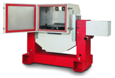
2-Axis Motion Simulator
| Positioning resolution | 0.00001 º |
|---|---|
| Position accuracy | < 1 arc sec |
| Rate resolution | 0.0001 º/s |
| Rate stability | ±0.0002 % < 400 °/s ±0.0005 % < 1000 °/s |
| Max. rate | 1000 º/s (inner axis) 400 º/s (middle axis) |
| Max. acceleration | 2700 º/s2 (inner axis) 260 º/s2 (outer axis) |
| Payload Capacity | 40 kg |
| Temperature range | -60 +90 ºC |
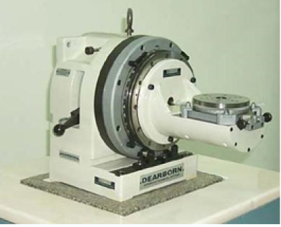
Index Table
| Positioning accuracy | 0.25 arcsec |
|---|---|
| Repeatability | 0.05 arcsec |
| Position stability | 0.025 arcsec |
| Orthogonality | 2 arcsec |
| Positioning resolution | 1.0 deg |
| Payload | 10 lbs |
| Dimensions | 2620 x 1755 x 1219 mm |
| Weight | 310 lbs |
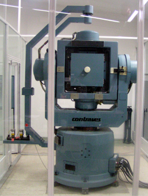
3-Axis Motion Simulator
| Positioning resolution | 0.00001 º |
|---|---|
| Position accuracy | < 1 arcsec |
| Rate resolution | 0.00001 º/s |
| Rate stability | 0.0001 % |
|
Max. rate |
1000 º/s (inner axis) 750 º/s (middle axis) 500 º/s (outer axis) |
| Max. acceleration | 1660 º/s2 (inner axis) 590 º/s2 (middle axis) 660 º/s2(outer axis) |
| Temperature range | -55 +85 ºC |
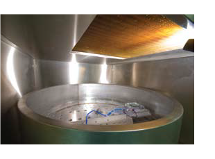
Centrifuge
| Positioning resolution | 0.00001 º |
|---|---|
| Positioning accuracy | < 1 arc sec |
| Rate resolution | 0.00001 º/s |
| Rate stability | 0.0001 % |
| Rate range | 4000 º/s |
| Linear acceleration range | 0.5-200 g |
| Payload Capacity | 10 kg |
| Temperature range | -60 to +125 ºC |
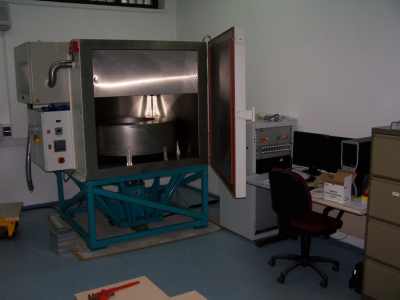
Technical specifications of gyroscope can be verified and calibration parameters can be found by these tests. Stability and temperature dependency of calibration parameters can be calculated using with gyroscope tests also. These tests are divided into two parts. First part is Allan variance tests and second part is calibration tests.
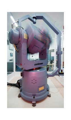 Allan Variance Tests
Data should be taken for long time (for hours) without giving input to the gyroscope. Allan variance is the average of the variance of adjacent pairs of elements in a contiguous time series of data versus the averaging time used to generate the elements. Allan variance results are related to basic sensor noise terms given below:
- Quantization Noise
- Angle Random Walk
- Bias Instability
- Rate Ramp.
Allan variance tests are performed by using indexing table (or dividing head), two axis position/rate table, three axis motion simulator.
Calibration Tests
Each gyroscope is calibrated separately by these tests. Calibration tests can be performed by using two axis position / rate table or three axis motion simulator Highly sensitive rate inputs can be given to the gyroscope using this equipment. Measurement range of the gyroscopes has been considered for the test inputs. Gyroscopes scale factor, misalignments and errors can be calculated as a result of rate inputs in all measurement range of gyroscope. Bias value is calculated by precision positioning of gyroscopes. Gyroscope calibration matrix is constituted with these calculated parameters and this matrix can be used during navigation process and IMU software. Calibration tests can be repeated to find the temperature dependence of the calibration parameters.
Sample Requirements
These tests can be applied to fiber-optic, laser and MEMs (Micro-Electro-Mechanical Systems) and vibrating types of gyroscopes.
Suitable test setup for gyroscope testing should be selected and configured. This test setup mainly includes sensor mounting fixture, software and electronic equipment required to operate gyroscope and measure its output. After the test setup is complete, test plan is prepared and the results of all measurements are reported.
Specifications of the Test and Measurement Equipment mainly used in these tests
2-Axis Motion Simulator
| Positioning resolution | 0.00001 º |
|---|---|
| Position accuracy | < 1 arc sec |
| Rate resolution | 0.0001 º/s |
| Rate stability | ±0.0002 % < 400 °/s ±0.0005 % < 1000 °/s |
| Max. rate | 1000 º/s (inner axis) 400 º/s (middle axis) |
| Max. acceleration | 2700 º/s2 (inner axis) 260 º/s2 (outer axis) |
| Payload Capacity | 40 kg |
| Temperature range | -60 +90 ºC |
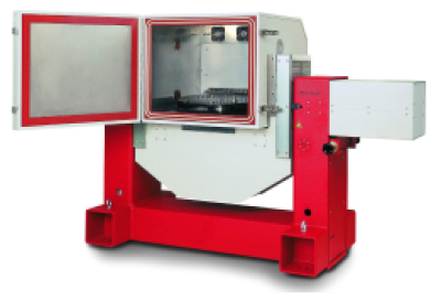
Index Table
| Positioning accuracy (arcsec) | 0.25 |
|---|---|
| Repeatability (arcsec) | 0.05 |
| Position stability (arcsec) | 0.025 |
| Orthogonality (arcsec) | 2 |
| Positioning resolution (deg) | 1.0 |
| Payload ( lbs) | 10 |
| Dimensions (mm) | 2620 x 1755 x 1219 mm |
| Weight (lbs) | 310 |
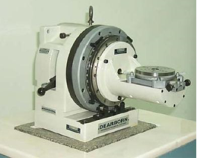
3-Axis Motion Simulator
| Positioning resolution | 0.00001 º |
|---|---|
| Position accuracy | < 1 arcsec |
| Rate resolution | 0.00001 º/s |
| Rate stability | 0.0001 % |
| Max. rate | 1000 º/s (inner axis) 750 º/s (middle axis) 500 º/s (outer axis) |
| Max. acceleration | 1660 º/s2 (inner axis) 590 º/s2 (middle axis) 660 º/s2 (outer axis) |
| Temperature range | -55 +85 ºC |
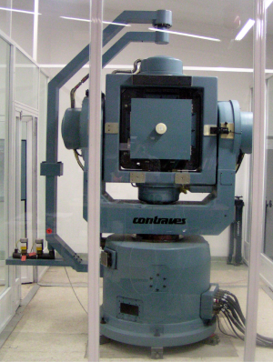
Centrifuge
| Positioning resolution | 0.00001 º |
|---|---|
| Positioning accuracy | < 1 arc sec |
| Rate resolution | 0.00001 º/s |
| Rate stability | 0.0001 % |
| Rate range | 4000 º/s |
| Linear acceleration range | 0.5-200 g |
| Payload Capacity | 10 kg |
| Temperature range | -60 to +125 ºC |

