Material Testing and Analysis Infrastructure was established in 2003 regarding the purpose of conducting R&D activities and prototype production of the materials and technologies with national capabilities which are critical in the space and aerospace industry. In particular, indigenous development of materials, components and special production processes , which are classified as critical and cannot be acquired from abroad, has been determined as the main goal and many national and indigenous products have been developed since then within the scope of this target.
Besides SAGE projects, within the facilities and capabilities of the KRITEK, R&D activities, production and industrial service are provided especially to the leading defense industry, space and aviation organizations, research institutes and universities in our country. The infrastructure, which has been constantly evolving in terms of its device capabilities since the day it was established, can respond immediately to all demands coming in and out of SAGE with its unique facilities.
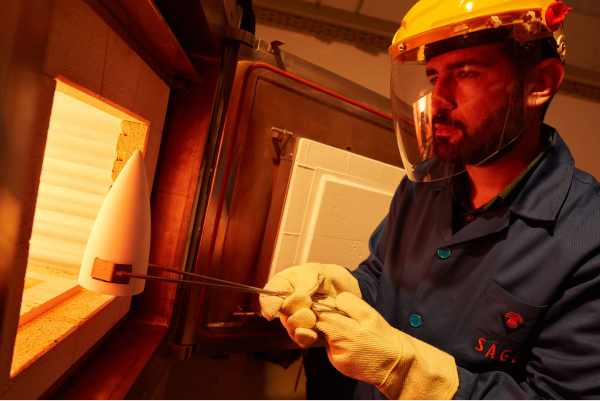
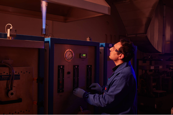
Furthermore, production and forming of various materials through powder metallurgy, vacuum metallurgy and thermomechanical techniques are conducted in KRİTEK. Correspondingly, mechanical, chemical and physical testing and characterization of materials are performed in the infrastructure. The laboratories in the KRITEK are given below:
- Heat Treatment Laboratories
- Thermomechanical Processing Laboratories
- Mechanical Production Laboratory
- Ceramics Laboratory
- Metallography Laboratory
- Powder Metallurgy Laboratory
- Coating Technologies Laboratory
- Antenna Technologies Laboratory
- Sensor Technologies Laboratory
- Electromagnetic Laboratory
- Mechanical and Physical Testing Laboratory
- Characterization Laboratories
In addition, the following material and testing services are provided to various industrial organizations universities and public institutions within the KRİTEK:
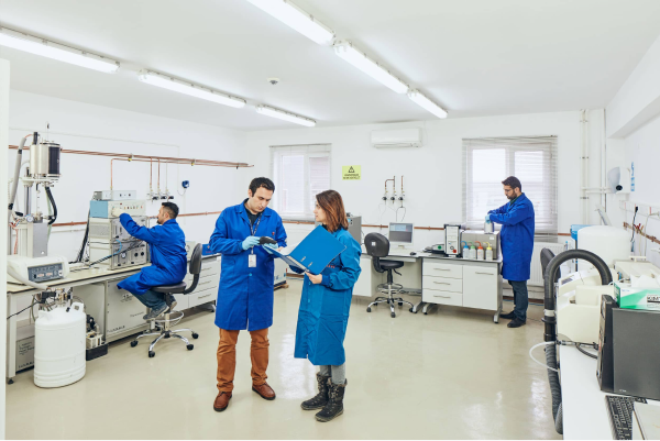
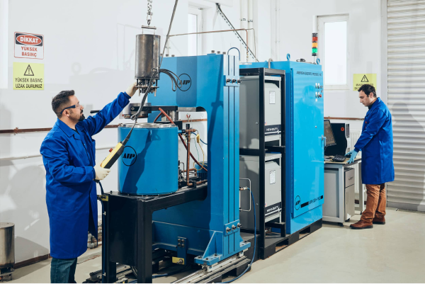
Brief İnformation: Thermal expansion coefficient measurement tests are carried out with the high temperature dilatometer device in the TÜBİTAK SAGE infrastructure. The dilatometer device has a vertical sampling shape and can be used for all metallic and ceramic materials between -150 °C and 1750 °C. As a result, the device gives graph that shows the variation of sample size with temperature. The graph is used to calculate the coefficient of thermal expansion of materials.
Device: High Temperature Dilatometer Device (L75, Linseis)
Technical Property: The dilatometer can measure under different atmospheres. As a result, the device gives graph that shows the variation of sample size with temperature. The graph is used to calculate the coefficient of thermal expansion of materials.
Standards Covered/Specifications: Measurements are performed by taking into account the ASTM E228 standard. The standard sample is a cylindrical sample that have ø6mmx20mm dimensions or a square sample that not exceeding these dimensions.
Special Conditions: Materials containing explosives are not tested.
Brief İnformation: Carbon (C) and Sulfur (S) determination tests are carried out in accordance with the combustion method. In the test, the sample is burned under an oxygen atmosphere and the carbon and sulfur in the samples are isolated separately and measured by appropriate methods.
Device: LECO CS230 Carbon / Sulfur Analysis Device
Technical Property:
- Heating Method: Induction Heating
- Measurement Method: Infrared absorption (for both carbon and sulfur)
- Measuring Range (per 1 gram)*:
- Karbon: 4 ppm - 3.5 wt%
- Sulfur: 4 ppm - 0.4 wt%
- Measuring range can be extended by reducing sample weight
- Sample weight: 1 g nominal (Suitable sample weight may vary depending on the material to be tested)
Standards Covered/Specifications: Carbon and sulfur determination tests can be performed in accordance with the relevant standards that are given below:
ASTM E 1019: Standard Test Methods for Determination of Carbon, Sulfur, Nitrogen, and Oxygen in Steel and in Iron, Nickel, and Cobalt Alloys
ASTM E 1491: Standard Test Method for Determination of Carbon in Refractory and Reactive Metals and Their Alloys by Combustion Analysis
Special Conditions: Inorganic materials that are non-volatile and non-explosive can be tested with the device (metals, ceramics, ores etc.)
Brief İnformation: Hydrogen, Nitrogen and Oxygen determination tests are according to inert gas melting method. The sample is melted under an atmosphere of helium gas and hydrogen, nitrogen and oxygen in the samples are isolated separately and measured by appropriate methods.
Device: LECO TCH600 Hydrogen/Nitrogen/Oxygen Analysis Device
Technical Property:
- Heating Method: Resistive Heating in Electrode Furnace
- Measurement Method:
- Hydrogen: Infrared Absorption
- Nitrogen: Thermal Conductivity
- Oxygen: Infrared Absorption
- Measuring Range (per 1 gram)*:
- Hydrogen: 0.1 ppm - 0.25 wt%
- Nitrojen: 0.05 ppm - 3.0 wt%
- Oxygen: 0.05 ppm - 5.0 wt%
- Measuring range can be extended by reducing sample weight
- Sample weight: 1 g nominal (Suitable sample weight may vary depending on the material to be tested)
Standards Covered/Specifications: Hydrogen, Nitrogen and Oxygen determination tests can be performed in accordance with the relevant standards that are given below:
ASTM E 1019: Standard Test Methods for Determination of Carbon, Sulfur, Nitrogen, and Oxygen in Steel and in Iron, Nickel, and Cobalt Alloys
ASTM E 1409: Standard Test Method for Determination of Oxygen and Nitrogen in Titanium and Titanium Alloys by Inert Gas Fusion
ASTM E 1477: Standard Test Method for Determination of Hydrogen in Titanium and Titanium Alloys by Inert Gas Fusion Thermal Conductivity/Infrared Detection Method
Special Conditions: Inorganic materials that are non-volatile and non-explosive can be tested with the device. (Metals, ceramics, ores etc.)
Brief İnformation: In the macro examination, grain edges on the part, unwanted formations for pollution are observed and their sizes can be measured. In the microstructure examination, the microstructure of the material is examined and information is obtained about the mechanical properties, previous processes of the material and production methods.
Device: Zeiss Axioskop MAT 2
Technical Property: The device works in room conditions. In order to get healthy results and measurements, the flatness and parallelism properties of the sample should be well enough. Samples should be mounted for ease of sample cleaning and handling. To get best images, the sample should be etched with a suitable etcher.
Standards Covered/Specifications: ASTM E3, ASTM E407, ASTM E340, ASTM E45
Special Conditions: The sample must be solid and stable at room temperature.
Brief İnformation: It is used to measure the particle size distribution of samples of solids, emulsions, dry powder dispersed in liquid.
Device: Malvern Mastersizer 2000
Technical Property:
Grain size range: 0.02 – 2000 microns
Measuring principle: Mie scattering
Detector system: Red light: front scattering, edge scattering, back scattering
Blue light: Wide angle front and rear dispersion
Source of light: Red light: Helyum neon laser
Blue light: Solid state light source
Optical alignment system: Fast automatic alignment system with dark field optical indicator
Laser system: Mastersizer 2000: Class 1 laser
Auotosampler 2000: Class 2 laser
Standards Covered/Specifications: -
Special Conditions: -
Brief İnformation: Coating thickness test is performed to determine the thickness of metallic coatings on materials. The test sample is placed inside the X-Ray Fluorescence Analyzer with the coating surface exposed. The type of coating and material is selected from the pre-coded library. The X-ray is sent to the material and the amount of coating thickness on the material is determined according to the beam bouncing back from the material.
Device: X-Ray Fluorescence Analyzer
Technical Property: To measure coating thickness, the ambient temperature must be approximately 25 °C. The length of the sample should be no more than 30 cm and its weight should be no more than 2 kg. Larger pieces need to be cut to suitable sizes before coating thickness measurement.
Standards Covered/Specifications: Tests can be carried out in accordance with all military and civilian standards that are suitable for the technical features of the X-Ray Fluorescence device.
Special Conditions: In order to measure the coating thickness, the type of coating and the type of material must be known. The coating thicknesses that have been previously uploaded to the library can be measured immediately. Updates should be made for the coating types that are not in the library and the measurement can be performed after the updates are made.
Brief İnformation: The hardness test gives information about the durability, strength and abrasion resistance of the material and it is used to determine whether this material needs heat treatment or to check the accuracy of the heat treatment. Hardness is calculated by immersing the specially sized tips into the material.
Device: For macro hardness: Struers Duramin-500
For micro hardness: Emco-Test DuraScan 20 G5
Technical Property: The size of the sample and the type of material are determined by which hardness measurement method will be used. Surface preparations are indicated in Table-1.
Table 1. Surface requirements of Hardness Tests.
| Test | Surface Preparations |
| Rockwell HR |
Macro Hardness Test No surface preparation is required. |
| Brinell HB |
Macro Hardness Test Sandpapering Micro Hardness Test Polished |
| Vickers HV |
Macro Hardness Test Flat surface Micro Hardness Test Mechanical and electro polished |
| Knoop HK |
Micro Hardness Test Mechanical and electro polished |
Standards Covered/Specifications: The standards covered by the test methods are given in Table-2.
Table 2. Hardness test methods and standards covered.
| Hardness Test Method |
Standard |
| Vickers |
ISO 6507 ASTM E384 ASTM E384 |
| Knoop |
ISO 4545 ASTM E384 |
| Brinell |
ISO 6506 ASTM E10 |
| Rockwell |
ISO 6508 ASTM E18 |
Special Conditions: -
